A cylinder on an inclined plane
Task number: 550
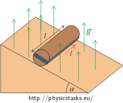
A cylinder of mass m = 250 g and length l = 10 cm is placed on an inclined plane of a rake angle α = 30 °. A 10-turn loop of wire is wound around the cylinder in the longitudinal orientation. The cylinder is situated in a magnetic field of an induction B = 0.5 T. The magnetic field is oriented vertically as shown in the figure.
Determine the minimal electric current flowing through the coil that prevents a movement of the cylinder down the inclined plane.
Hint
Draw a free body diagram with all forces acting upon the cylinder. Determine the directions of the moments of force.
Analysis
The gravitational force acts upon the cylinder with a coil and it brings about a movement of the cylinder down the inclined plane. The rotary axis lies on the contact between the cylinder and the plane. The effect of the gravitational force can be characterized by a moment of force.
Thanks to the current flowing through the coil in the suitably selected direction and thanks to the fact that the coil is placed in the magnetic field, magnetic forces act upon the sides of the coil. The directions of the forces are determined by the Fleming’s left-hand rule.
The magnetic forces act on the coil as well as on the cylinder by the moment of force.
The vector sum of all moments of force related to the rotary axis has to be zero to keep the cylinder in motionlessness.
The moment of force caused by the magnetic forces has to have an opposite direction compared to the direction of the moment of force that is caused by the gravitational force. And the vector sum of both moments of force has to be on the equal size, as well. These conditions are affected by the direction of the current flowing through the coil and by the global geometrical arrangement of the system.
Solution
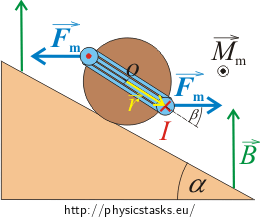
The gravitational force \(\vec{F}_G\) causes the rolling of the cylinder down the inclined plane. The moment of force \(\vec{M}\) is expressed as
\[\vec{M}=\vec{r}\times \vec{F}_G,\]where the length of the moment arm is equal to the radius of the base of the cylinder.
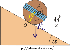
The direction of the rotary moment is determined by the right-hand rule and it falls outside the picture area .
The size of the moment of force is equal to:
\[M=rF_G \sin\,\varphi,\]where φ is an angle between vectors \(\vec{r}\) and \(\vec{F}_G\). The value of sin φ is the same as the value of sin α:
\[\sin\varphi=\sin\alpha,\]where α is the rake angle of the inclined plane. This equality may occur because the angle α corresponds with the supplementary angle to the angle φ.
The rotary axis lies on the contact between the cylinder and the plane (look at the picture).
The gravitational force is:
\[F_G=mg.\]The size of moment of force caused by gravitational force gives an expression:
\[M=rmg\,\sin{\alpha}.\]We want the cylinder to stay at rest. Therefore some force must act on the cylinder. The size of the moment Mm of this mentioned force has to be equal to the size of the mechanical moment of gravitational force. However, directions of these moments have to be opposite. That means:
\[M=M_m.\]Now we have to investigate the forces acting on particular parts of the rectangular coil placed in a magnetic field.
The size of forces acting on particular parts of the rectangular loop can be determined by the relation:
\[F_m=I|\vec{l}\times\vec{B}|=IlB\,\sin\varphi,\]where φ is an angle between the vector of magnetic induction \(\vec{r}\) and the direction of the current.
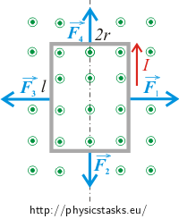
Magnetic forces acting on the sides of the coil parallel to the picture
The forces acting upon the shorter sides of the rectangle (the sides that are parallel to the picture) have equal sizes but opposite directions. The forces cancel each other out. The connecting line of the points of force applications lies in the axis of the loop . Therefore the final moment of force will be zero as well. The forces acting on the shorter sides don’t help to the rotation then.
Magnetic forces acting on the sides of the coil perpendicular to the picture
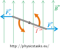
The sizes of the forces acting on the sides that are perpendicular to the picture are equal and have opposite directions. For this reason these forces can’t bring the loop into translation movement. However, these forces don’t lie in one line, so they create a nonzero final moment of force. It’s a case of so called couple – a system of forces with a resultant momentum but no resultant force. Moment of the couple is independent of choice of the rotary axis.
Note: Detailed description and pictures are stated in the solution of the hint.
The direction of current going through the part of coil that is perpendicular to the picture forms a right angle with the vector of magnetic induction. It means φ = 90 °. The size of magnetic force acting on a conductor of length l is:
\[F_1=F_2=BIl\,\sin\,90^{\circ}=BIl.\]The coil contains N loops of wire. Therefore the final force acting on one side of the coil is:
\[F_m=NBlI.\]Neither the size nor the direction of this force is changed during the rotation of the cylinder.
The moments of both magnetic forces have the same direction (out of the picture). They are perpendicular to the plain given by both forces. The final moment is:
\[M_m=2rF_m \sin\beta,\]where β presents an angle between vector \(\vec{r}\) and magnetic force \(\vec{F}_m\). This angle changes during rotation of the cylinder. Maximal value of the sin β comes when the coil is in vertical position, i.e. β = 90 ° and sin β = 1. The value of the moment acting on the coil will be maximal in this position. Afterwards we can express the minimal electric current going through the coil.
After substitution of the value of the magnetic force Fm, we obtain an expression to count the value of the maximal moment Mmax:
\[M_\mathrm{max}=2rBlIN.\]The value of moment of gravitational force has to be equal to the value of the moment of the magnetic force so that the cylinder stays at rest and does not move down the plane. It means:
\[M=M_\mathrm{max},\] \[rmg\,\sin\alpha=2rBlIN.\]Now we can express the unknown electric current I:
\[I= \frac{mg\,\sin\alpha}{2BlIN}.\]It is the minimal current running through the coil to keep the coil not-running down the plane.
Numerical solution
\[m=250\,\mathrm{g}=0.25\,\mathrm{kg}\] \[l=10\,\mathrm{cm}=0.10\,\mathrm{m}\] \[N=10\] \[B=0.50\,\mathrm{T}\] \[\alpha=30^{\circ}\] \[I=?\]From the physical tables:
\[g=9.81\,\mathrm{m\,s^{-2}}\]
\[I= \frac{mg\,\sin\alpha}{2BlN}=\frac{0.25{\cdot} 9.81\cdot \sin30^{\circ}}{2{\cdot} 0.50{\cdot} 0.10{\cdot} 10}\,\mathrm{A}\dot{=}1.2\,\mathrm{A}\]Answer
The current flowing through the coil is approximately I = 1.2 A to keep the cylinder in the motionlessness (if it is supposed that the coil lies in a vertical plane in the initial position). If the current flowing through the coil was larger, the cylinder in an appropriate position would start to move up.
