Measurement of the Malusʼ law
Experiment number : 4298
Goal of experiment
The goal of this experiment is to quantitatively verify the validity of Malus’ law.
Theory
This experiment will focus on a situation in which linearly polarised light is incident on and passes through a generally rotated linear polarising filter. Malus’ law gives an answer to the question about what will be the intensity of the transmitted light depending on the rotation of the polarising filter. If the plane in which the polarising filter passes is rotated relative to the plane of the incident polarised light by an angle \(\varphi\), then the following applies:
\[I(\varphi)=I_0\cos^2\varphi,\]where \(I_0\) is the intensity of the incident light and \(I\) is the intensity of the transmitted light.
A well-known special case of Malus’ law is the situation where the plane passed through the polarising filter is oriented perpendicular to the plane of polarisation of the incident light. In such a case, \(\varphi=90^\circ\) and hence \(I=0\); the polarising filter, therefore transmits no light. Such a situation is qualitatively investigated in the Linearly Polarised Light LCD Monitor experiment Linearly polarized light of LCD.
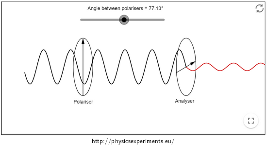
An illustration of what happens to the intensity of the transmitted light when the angle \(\varphi\) changes is provided by an animation created in GeoGebra by Chris Hamper:
.Equipment
Light source, one ordinary and one rotating polarising filter, luxmeter.
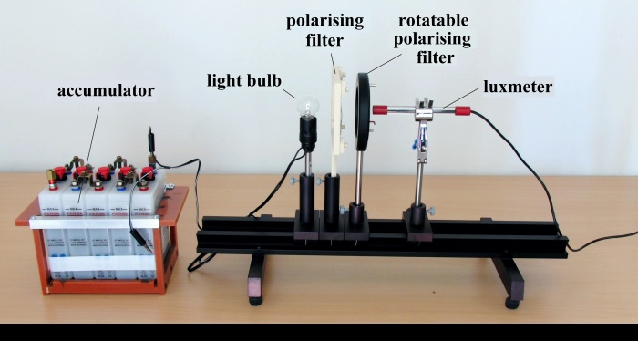
Choosing a luxmeter: Measurements can be made with either a luxmeter, which is strongly directional, or a luxmeter, which collects light from the entire half-space. In our sample case, the measurement was made with a Vernier LS-BTA directional luxmeter, but very similar results were also obtained with a Voltcraft BL-10L luxmeter (Figure 2), which collects light from the entire half-space.
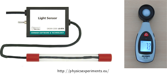
Selection of light source: It is essential for the measurement that the light source provides a constant, unvarying luminous flux. For this reason, it is not appropriate to use, for example, an incandescent light bulb powered by ordinary (flat, pencil) batteries – these discharge over time and the light output from the bulb decreases measurably. Similarly, you cannot use AC power supplies that provide a variable voltage and the connected light source does not shine continuously, but actually flickers at a high frequency (this is a common feature of mains-connected luminaires – see for example this experiment). However the same feature can also be observed in luminaires connected to some DC sources which imperfectly smooth the input mains voltage to the output DC voltage. In other words, it is essential to pay considerable attention to the choice of source and to test it beforehand.
For the purposes of our measurements, it worked very well to connect a 6 V bulb to an accumulator, where the voltage drop is negligible within minutes. Similarly, a high-brightness diode can be used.
Procedure
Arrange the light source, the two polarising filters and the luxmeter in a row – Figure 3. Place both filters and luxmeter as close together as possible to minimise the amount of light entering the luxmeter from the surroundings (daylight, unwanted reflections from walls, etc.).
Turn on the light source and set the rotating filter so that the illumination intensity measured by the luxmeter is maximum (i.e., both filters transmit the same plane of polarisation).
Now rotate the movable filter gradually (for example, in 5° steps) and note the measured intensity value for each position.
Make measurements over a rotation range from 0° to 90° or up to 180°. Then plot the obtained values on a graph.
Example of results
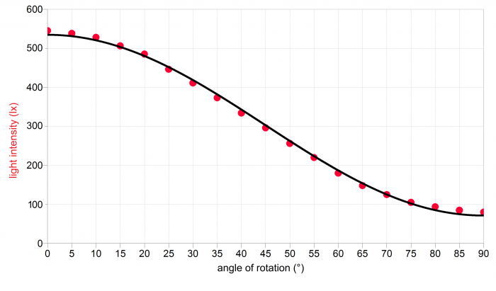
A sample of the measured data is given in the table below and the graph in Figure 4. The obtained values are plotted with a function of the form \(I(\varphi)=I_0\cos^2\varphi+K\), which indicates a reasonable match between the measured data and the theoretically predicted trend.
Table of measured data:
rotation angle \(\varphi\) (°) 0 5 10 15 20 25 30 35 40 45 50 55 60 65 70 75 78 85 90 intensity I (lx) 545 538 528 506 485 446 411 373 334 296 256 220 180 148 125 105 94 85 80 Technical notes
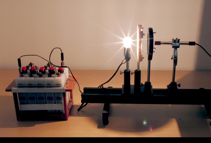
In the graph in Fig. 4, it can be noticed that even for an angle of 90°, the measured illuminance does not drop to zero as the relationship in the Theory section predicted. This is because not only light passed through the polarising filters but also ambient light or reflected light from the bulb enters the luxmeter − for example, in Figure 5 it can be seen that some of the light from the bulb is reflected into the luxmeter from the adjacent wall.
The above effect, i.e. the trapping of light entering the luxmeter outside the polarising filters, can be eliminated in several ways:
darkening the room
placing the apparatus away from walls that would reflect the light
placing the polarising filters and the luxmeter as close together as possible
These recommendations are more important to follow when working with a full-space luxmeter; a directional luxmeter is less prone to unwanted interception of ambient or reflected light.
Methodical notes
It should be emphasised that Malus’ law applies to linearly polarised light. If we let natural, i.e. unpolarised, light fall on the filter, we always measure half the intensity behind the filter than in front of it, regardless of the rotation of the filter.
