Light Bulb Current-Voltage Characteristic
Experiment number : 2097
Goal of experiment
The goal of this experiment is to show the dependency of voltage on current when measured on a light bulb (i.e. its current-voltage characteristic). This task is suitable as a problem task – students can present their hypotheses explaining the non-linearity of the current-voltage characteristic of a light bulb. Afterwards they can verify their hypotheses with the teacher's help.
This experiment is followed by a quantitative task that deals with the resistance of the light bulb filament.
Theory
According to Ohm’s law, there is a linear dependency between the current flowing through a wire and the voltage between the ends of the wire. The constant of proportionality is called conductance \(G=\frac{1}{R}\), where R is the wire resistance:
\[I=\frac{1}{R}\cdot U\tag{1}\]
In this experiment we measure how the voltage depends on the current, therefore we use Ohm’s law in the form of:
\[U=R\cdot I\tag{2}\]
The resistance of a wire depends on the dimensions of the wire the material it is made of (see the Dependence of Wire Resistance on Its Parameters experiment), and its temperature:
\[R=R_0(1+\alpha\Delta t),\tag{3}\]
where α is the resistance temperature coefficient and Δt is the difference between initial and final temperatures. From the equation (3) we can see that the resistance of a wire increases with increasing temperature.
Electric power of the light bulb is given by the product of voltage and current:
\[P = U\cdot I\tag{4}\]
By substituting from Ohm's law we obtain:
\[P = \frac{U^2}{R}.\tag{5}\]
Provided that we know the voltage and the power, we can determine the resistance of the light bulb filament (at “factory conditions”):
\[R = \frac{U^2}{P}.\tag{6}\]
Tools
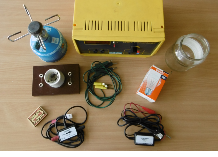
- 230 V light bulbs with a socket
- Controllable power supply with up to 10 V output (or a constant voltage source and an adjustable resistor of ca. 100 Ω
- Voltmeter and ammeter
- Connecting wires, crocodile clips
- Gas burner, matches
- Jar
It is recommended to perform the experiment with digital voltmeter and ammeter connected to a computer; without the need to write down measured values, the measurement is much faster and students can use the saved time for inquiry-based discussion. However, it is also possible to use multimeters.
The first part of the experiment can be performed with an ordinary light bulb (e.g. 3.5 V/0.3 A), however, since it is necessary to remove the glass bulb to verify the hypotheses, it is recommended to use the 230 V light bulb from the beginning.
Procedure
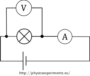
We connect the circuit according to the circuit diagram – we connect the bulb and ammeter in series to the voltage source, then we connect the voltmeter to the bulb in parallel.
We plot the dependence of voltage on current.
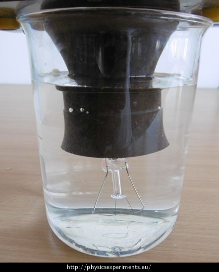
We discuss the non-linearity of the voltage-current characteristic with students. It is caused by the dependence of the bulb filament resistance on its temperature. Then, we remove the glass bulb and submerge the filament in water (more detailed description below) to ensure a constant temperature of the filament. We preform the experiment again.
As a conclusion, students should determine the bulb filament resistance from the I-V curve. Their results can be compared with the resistance determined from the information written on the light bulb. Once again, it is recommended to discuss the measured resistance.
Sample result
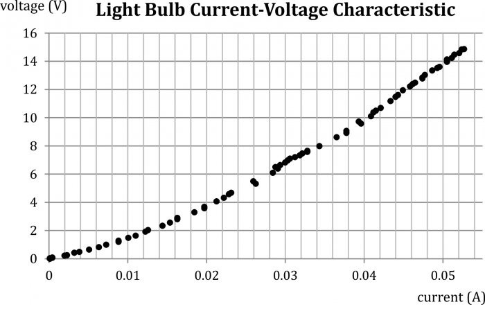
Our measurement was performed with a 240 V/60 W light bulb. Measured values are plotted in the graph below (Fig. 3).
From the graph we can observe that the dependence is non-linear, with increasing current the slope of the curve increases, and so does the wire resistance.
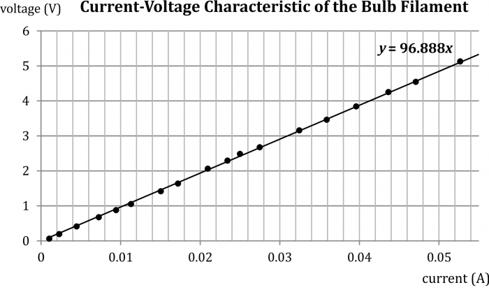
The measurement without the glass bulb with filament submerged in water is shown in a graph in Figure 4 – in this case, the current-voltage characteristic is linear and the wire resistance is approximately 97 Ω.
Removing the bulb
The procedure to removing the bulb, so that we are able to submerge the bulb filament in water and thus ensure its constant temperature, is shown in the video below. First, we heat the socket of the glass bulb for several seconds using a burner. Then we immerse the bulb in cold water. The thermal shock causes the bulb to crack and separate from the socket. It is recommended rotating the bulb during heating to ensure that it is heated evenly along the whole circumference.
Note: It is possible to hold the light bulb in bare hands during the heating. Glass is a bad heat conductor, so the rest of the bulb does not heat much.
For the second measurement, we submerge the remains of the light bulb (i.e. the bulb filament with the socket) into a jar filled with cold water. This will dissipate the heat generating by the filament.
Resistance at "factory" conditions
We performed the experiment with a 240 V/60 W light bulb. The wire resistance determined by the current-voltage characteristic is approx. 97 Ω.
The resistance can also be determined from the information given by the manufactures according to the relation (6):
\[R = \frac{230^2}{60}\ \Omega = 882\ \Omega \]
This discrepancy is another proof that wire resistance depends on its temperature – the working temperature of the bulb filament is higher than the temperature of the water we used to cool it.
Pedagogical notes
This experiment is suitable to be submitted as a problem task – the first measurement should be followed by a discussion of the fact that the I-V curve is non-linear, even though there is only a wire inside the bulb. Among the hypotheses, there should be one about the fact that a wire resistance also depends on something else, e.g. on temperature. Students should be able to find out that to obtain a linear I-V curve, we need to ensure a constant wire temperature. The teacher can then show them a way to conduct the experiment and repeat the measurement.
It is good to let the students determine the filament resistance from the I-V curve and from the power written on the bulb. The students can the discuss the obtained resistance. They can see that the resistance depends on the temperature of the conductor (and that a working temperature of a light bulb is much higher that the temperature at wich we performed the experiment).
If you want to use what is left of the light bulb, you can connect the bulb filament to the main power circuit (see video). The filament burns up very quickly, which demonstrates the necessity to cover the wire with a glass bulb filled with inert gas).
Technical notes
Be careful! Removing the glass bulb should be done by a teacher, so should be the second measurement with bare filament. There is a risk of burning and cutting yourself from the glass remains.
Given the fact that the experiment is performed using low voltage, it does not matter if a small amount of water remains in the bulb socket.
The bulb filament is very fragile; it can break when handled without care.
A glass jar has proven to be suitable as a water container. Some glass beakers can break after immersing the hot bulb filament.
