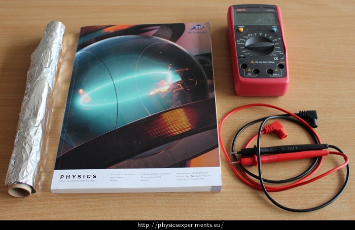
Plate Capacitor
Experiment number : 2122
Goal of experiment
The experiment shows the dependence of capacitance of a plate capacitor on the surface area and the distance between the plates.
Theory
Capacitance C of a conductor expresses the ability of the conductor to accumulate electric charge. It is defined by the ratio of charge Q of and insulated conductor and its potential φ:
\[C=\frac{Q}{φ}.\]The capacitance of an isolated conductor is much smaller than the capacitance of a set of two conductors separated by a thin layer of air or a dielectric. Such a system is called a capacitor. The simplest capacitor is a plate capacitor consisting of two parallel plates with effective area S a distance d. If we connect this capacitor to a power source, the plate with higher potential will be charged with a positive charge +Q, and the other plate with negative charge -Q.
Capacitance of a plate capacitor is given by:
\[C=\varepsilon_\mathrm{0}\varepsilon_\mathrm{r}\frac{S}{d},\]where ε0 ≈ 8.85·10-12 C2·N-1·m-2 is the vacuum permittivity and εr is the relative dielectric permittivity. The relative permittivity of air is εr ≈ 1. In this experiment we use a book page as a dielectric.
Capacitance of a spherical conductor with radius R is \(C=4\pi\varepsilon_\mathrm{0}\varepsilon_\mathrm{r}R\). For every 1 cm of the radius of a spherical conductor, capacitance increases by approximately 1 pF, while capacitance of a capacitor made from an A4 book is in order of hundreds of pF.
Tools
Procedure
Dependence of capacitor capacitance on plate distance
Put two sheets of aluminium foil into the book so that there are twenty pages between them.
Connect the foils to the capacitance meter and measure the capacitance.
Now place forty sheets of paper between the aluminium foils and measure the capacitance.
Add another twenty sheets of paper between the foils (60 in total). Compare the measured values for a different number of sheets between the aluminium foils.
Dependence of capacitor capacitance on the effective surface area
Fold one aluminium foil in half and measure the capacitance of this capacitor.
Gradually reduce the surface area of the aluminium foil and measure its capacitance.
Compare the measured values for different surface areas.
Sample result
A sample result is illustrated in the video below.
The range of the capacity meter is set to 20 nF. The measured values are summarized in the following tables.
Number of pages C [pF] 35 390 85 220 128 190
Effective surface area C [pF] \(1 S\) 390 \(\frac{1}{2} S\) 210 \(\frac{1}{4} S\) 150 \(\frac{1}{8} S\) 100 From of the measured values we can observe that with more pages between the aluminium foils (i.e. with increasing distance), capacitance decreases. If we increase the surface area of the capacitor plates, its capacity increases. If we made a more accurate measurement and plotted the values into a graph, we would see that capacity is directly proportional to the surface area of the plates, and inversely proportional to the distance between the plates.
Technical notes
This measurement is greatly affected by how strongly we compress the book, or whether the aluminium foils are placed in the top or bottom part of the book.
The capacitor capacitance with a plate of A4 format is in order of hundreds of pF.
The aluminium foils should not be in contact during the measurement to avoid measurement errors.
Pedagogical notes
In the second part of the experiment we can show the difference between the area of individual plates and the effective surface of the capacitor (overlapping area). If we change only the relative position of the two aluminium sheets, we can see how the capacity of the capacitor changes. From here we can see that in the relation for the capacitance of the plate capacitor, S appears to be an effective area.


