Interaction of Wires with Current
Experiment number : 2098
Goal of experiment
The experiment demonstrates a mutual magnetic effect of two parallel conductors carrying current.
Theory
Magnetic field is generated around a wire when current flows through it. If we place a second wire carrying current parallel to the first wire into this magnetic field, these magnetic fields will interact with each other and the conductors will be subjected to magnetic forces.
The magnetic induction lines form concentric circles around each of the conductors. Their direction can be determined by Ampere's right-hand rule:
If we place our right hand on the wire so that the thumb shows the conventional current direction (from + to –), then the fingers indicate the direction of the magnetic induction lines.
Using Fleming’s left-hand rule, we can find the direction of the magnetic force one conductor acts on the magnetic field of the second conductor:
If we place an open palm of our left hand on the conductor so that the fingers show the conventional current direction and the magnetic induction lines enter our palm, the outstretched thumb shows the direction of the force with which the magnetic field acts upon the wire carrying current.
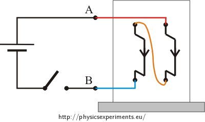
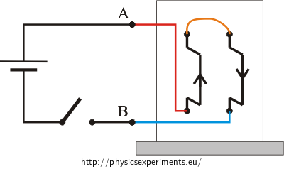
If the currents in both wires flow in the same direction, the forces acting on the two wires are attractive and they will move towards each other. Conversely, if the currents flow in the opposite directions, the forces will be repulsive and the wires will pull away.
A more detailed analysis of the direction and magnitudes of these forces is, along with a quantitative calculation, given in the task Magnetic Force between Two Wires Carrying Current.
Tools
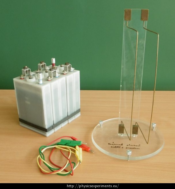
- parallel movable wires in a tripod
- battery 6 V
- connecting wires

Procedure
We connect the wires in series and connect them to the power supply via a switch. The experiment is performed in two steps:
- We connect the upper clamp of the first wire with the lower clamp of the second wire. The two remaining terminals are connected via a switch to the power supply. In this arrangement, the currents in the wires flow in the same direction. Turn on the switch and observe that the wires move closer to each other.

- We connect the upper clamps of the wires. Lower clamps are connected via the switch to the power supply. In this arrangement, the currents in the wires flow in the opposite direction. We move the wires within several millimetres of each other, turn on the switch and observe that the wires are repelled.

Sample result
A sample experiment can be seen in the following videos:
1) Currents flow in the same direction, the wires are attracted to each other.
2) Currents flow in the opposite direction, the wires are repelled from each other.
Technical notes
- The wires are in a shorted circuit, a relatively large current flows through them. Do not leave the circuit connected to a power supply for a long time.
- Parallel wires can be replaced with two freely suspended aluminium foil strips.


