Stirling Engine
Experiment number : 1949
Goal of experiment
We will show the operation of a Stirling engine, configured both as a heat engine and as a heat pump.
Theory
Stirling engine belongs to a family of closed-cycle heat engines operating with a permanent working fluid. At the time of its conception (in 1816) it was a direct competitor to the steam engine, surpassing it mostly with its relatively high efficiency and silent operation. the efficiency of the current models can reach up to an efficiency of remarkable 40 % and the engine finds frequent use in powering low-power devices.
The two basic construction types are labeled alpha and beta.
An alpha-type Stirling engine consists of two separate cylinders, one hot and one cold. Each contains a power piston, which spins a flywheel. When operating as an engine, the hot cylinder is situated inside a heat exchanger with a higher temperature and the cold cylinder is situated inside a heat sink with a lower temperature. An animation describing the working of this model is available e.g. on Wikipedia.
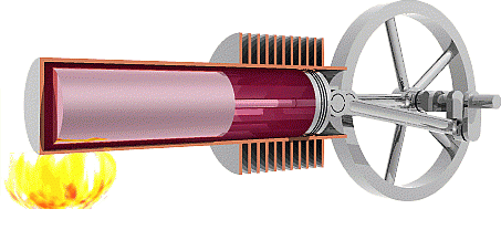
A beta-type Stirling engine consists of a single cylinder and when working as an engine, this cylinder is heated on one end and cooled on the other (e.g. with surrounding air). The single cylinder of the beta model contains a power piston, which spins a flywheel. In addition, it contains another piston, so called displacer. The displacer piston is loose-fitting and is designed to transfer the working fluid from one end of the piston to the other. Since we will use the beta model in our sample experiment, a picture (Fig. 1) depicting its appearance is included below; clicking the picture will start an animation demonstrating the machine work cycle (source: Wikipedia).

Construction type gamma exists as well, but it is not going to be addressed in detail here.
As an engine, the Stirling engine converts heat energy into mechanical energy. However, we can also use it as a heat pump (a cooling mechanism), which in turn converts mechanical energy into heat energy. By reversing the engine course, i.e. spinning it by supplying mechanical energy, a temperature difference between the ends of the cylinder arises without us cooling or heating either end; the temperature of one end increases and the temperature of the other end decreases.
Tools
Stirling engine (in the sample experiment we used the beta type), burner, matches, electric motor which spins the Stirling engine in the heat pump demonstration, thermal imaging camera
Procedure
First part of the experiment: Stirling engine as a heat engine
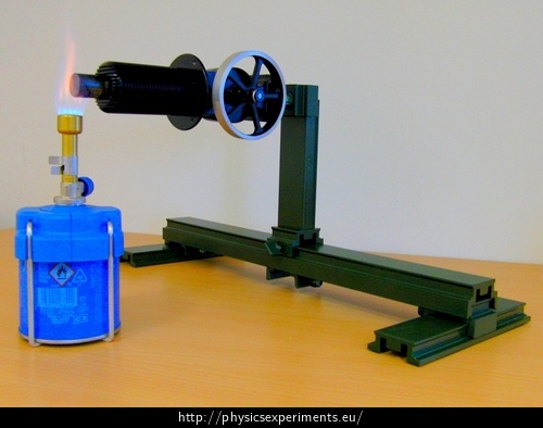
We secure the engine to a structural system and place the burner under the metal outlet of the cylinder.
We light the burner (Fig. 2) and let the metal heat for approximately 10 seconds (the proper time duration depends on the exact model of the engine).
If the engine does not start spinning of its own volition, we give it an initial impulse by turning the flywheel with our hand.
We observe the engine in operation and try to regulate its rotation speed by changing the intensity of the flame.
Second part of the experiment: Stirling engine as a heat pump.
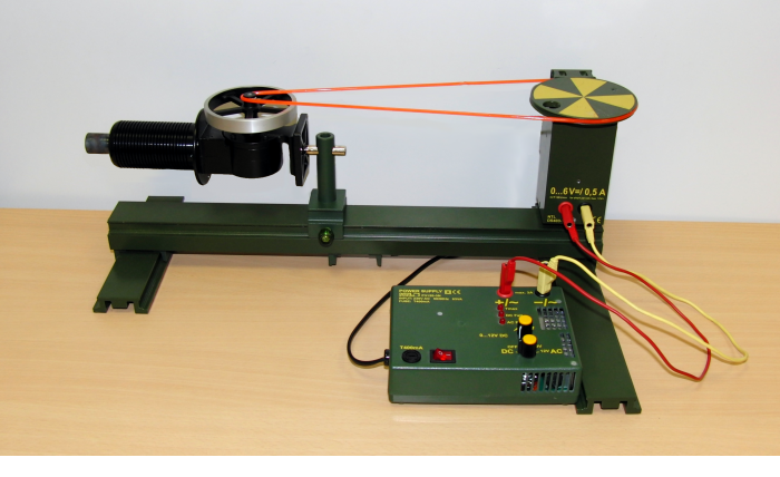
We connect the Stirling engine to an electric motor with a belt (Fig. 3). The electric motor is going to turn the engine.
We turn on the electric motor which spins the flywheel of the Stirling engine.
We observe the metal outlet of the engine cylinder (on the far left in Fig. 3) with a thermal imaging camera.
Sample result
First part of the experiment: Stirling engine as a heat engine
The opeartion of the Stirling engine as a heat engine is shown in video No. 1:
Video No. 1
Second part of the experiment: Stirling engine as a heat pump.
Video No. 2 illustrates the operation of the Stirling engine as a heat pump. The sequence provides overall view of the setup and then shows the metal outlet of the cylinder both in the visible spectrum (on the left) and in the IR spectrum (on the right). It is apparent that after the flywheel starts spinning, the temperature of the metal outlet of the cylinder is decreased. Conversely, a decrease in temperature can be observed on the opposite end of the cylinder (the heat sink). This effect is not captured in the video.
Video No. 2:
Technical notes
Stirling engine is sometimes sold primarily as an educational toy or a gift item. However, it can assist in teaching – at least in the first part of the experiment.
Safety warning: Follow the safety rules when working with the gas burner during the first part of the experiment.
Pedagogical notes
It is of course possible to present only the first part of the experiment, i.e. the working of a Stirling engine as a heat engine; that way, our tool requirements are greatly reduced, as we can spare the electric motor and the thermal imaging camera.


