Comparison of Heat Emitted from Incandescent and Energy Saving Light Bulbs
Experiment number : 4346
Goal of experiment
We will show the differences between heat radiated from an incandescent and an energy-saving bulb (more precisely, a compact fluorescent lamp) providing the same luminous flux.
Teorie
In an incandescent bulb, light is obtained by emission from a tungsten filament heated by passing electric current to a temperature higher than 2500 °C. However, only a fraction of the total electrical energy invested in the filament is converted into light, while the vast majority of it is radiated as heat in the form of infrared radiation. It is not surprising, that in response to efforts to regulate the use of such inefficient light sources, an idea was born to refer to incandescent bulbs as heaters - from a physical point of view, the emission of light from a tungsten filament is really only a minor side effect.
The term energy-saving bulb has been misapplied to light sources that are officially referred to as compact fluorescent lamps. As in the case of fluorescent lamps, these are low-pressure lamps filled with mercury vapour in which a glow discharge takes place, producing ultraviolet radiation. This is then converted into visible radiation by a phosphor deposited on the inner walls of the lamp.
To compare the efficiency of a light source, the so-called luminous efficacy K is usually used, [K] = lm/W, which expresses the luminous flux a light source provides per 1 W of its input power. While common values for conventional incandescent lamps are in the range of 10-15 lm/W, for compact fluorescent lamps it is 45-65 lm/W. From this comparison it can be seen that a conventional bulb sends significantly less energy from each watt of its power input into the light field than a compact fluorescent lamp; it therefore emits much more in the infrared, especially the thermal region, of the spectrum.
Light efficacy values can be easily estimated from the data given by light source manufacturers on the packaging of their products; in our experiment, for example, we use a conventional incandescent bulb with nominal parameters 700 lm/60 W (i.e. K ≈ 12 lm/W)) and a compact fluorescent lamp 700 lm/13 W (K ≈ 54 lm/W).
The problem of light sources and their properties is extensively addressed, for example, in the thesis Measuring the luminous efficacy of light sources (In Czech only).
Equipment
Thermal imaging camera, two identical lamps, an incandescent bulb and a compact fluorescent bulb providing the same luminous flux (in our case 60 W and 13 W, luminous flux in both cases is 700 lm).
Procedure
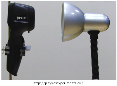
Place the lamps at a horizontal distance of about 15 cm from the thermal imaging camera (see Fig.1), switch them both on simultaneously and observe the heating of both light sources and their surroundings for several minutes.

Sample result
The successful execution of the experiment is illustrated in the video below. It can be seen that although the light sources provide a comparable luminous flux, an incandescent bulb emits much more energy in the form of heat.
In this video, the FLIR i7 thermal imaging camera was used. The temperature range of the colour scheme was set in the interval of 23 °C and 69 °C, the emissivity was ε = 0.95.
Technical notes
In the case of an incandescent bulb, the temperature will rise well above 100 °C during the experiment, so caution is necessary when removing the bulb.
Pedagogical notes
When carefully observing the heating of the incandescent bulb, it can be noticed that its temperature increases from the top, the bottom part is heated last. This situation can be used as a problem task for the pupils – why does the heating happen like this? If we repeat the experiment more than once, we can see that this is not a random phenomenon. After a while, students will probably come up with the correct explanation – i.e., that the gas inside the bulb (the protective atmosphere of the filament) is heated by the filament, its density decreases and thus it flows upwards, where the temperature incerases the most. This gives us a textbook example of heat exchange by advection.
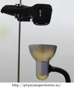
If we want to expand this further, we can now invite students to come up with a way to confirm this hypothesis – that it is an advection – experimentally. The simplest way to do this is to turn the bulb in the gravitational field so that its base is pointing down and the bulb is pointing up (see Figure 2), and again, use a thermal imaging camera to measure its heating (only this time it will be placed above the bulb). If the advection hypothesis was correct, the bulb should now heat up approximately evenly from the thermal imaging camera viewpoint.

Sample execution of this experiment is shown in Video 2.
Video 2:
When viewed from above, the bulb actually heats up evenly, while when viewed from the side we can observe the flow of the gradually heating protective atmosphere of the filament.
Thermal imaging camera basics – link to PDF
In this experiment, a thermographic measurement is used. The theory of thermography and basic recommendation and procedures that can help you obtain more accurate and undistorted results can be found in Experiments with thermal imaging camera (in Czech only).


